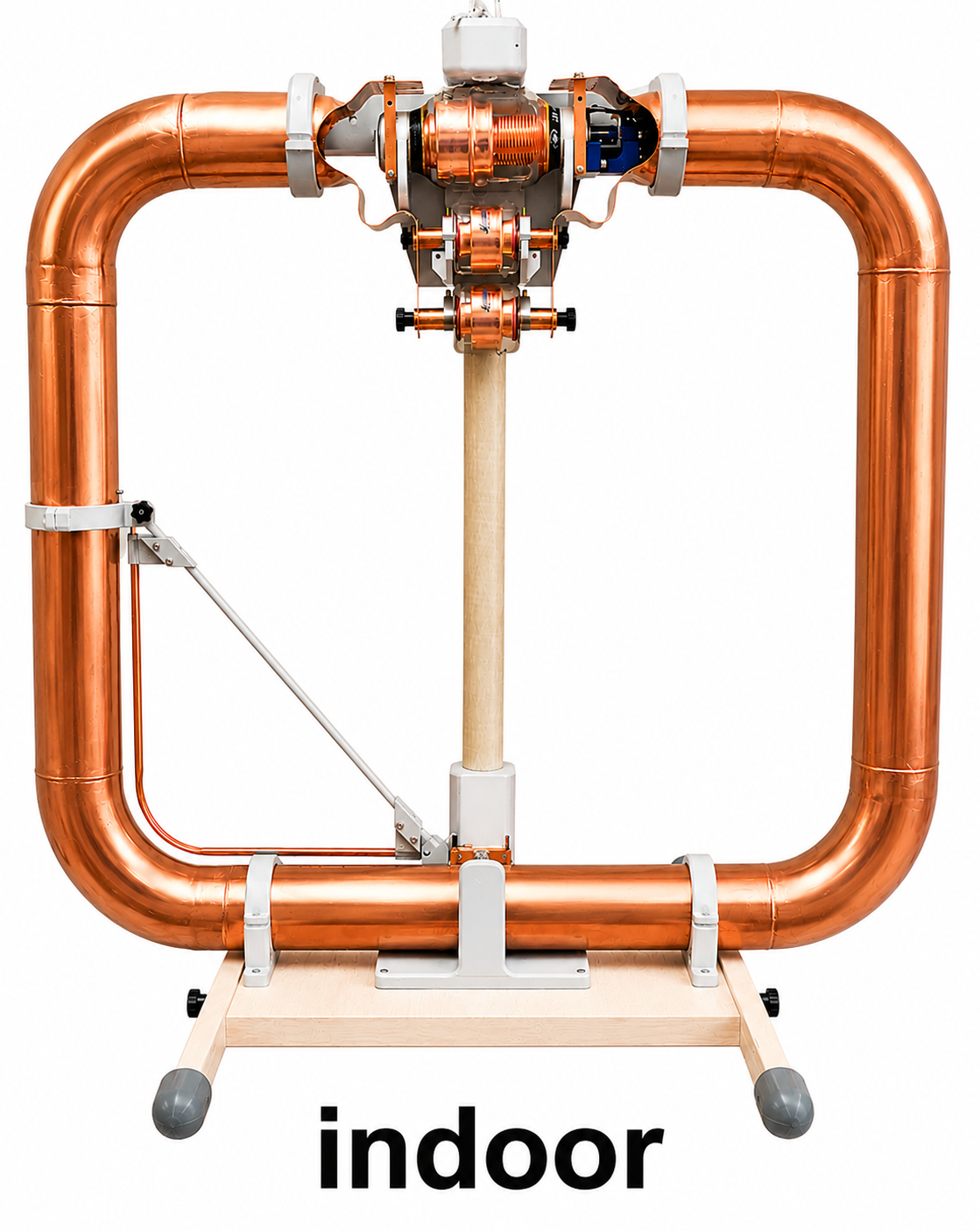
Info: Homebrew rectangular loop made of thick copper tubing with vacuum capacitors, 10 m to 160 m.
Conductor: Copper tube 100mm
Capacitor: Vacuum Capacitor
Environment: Placed in an upstairs room of a timber-frame house, 0.8 m above the floor.
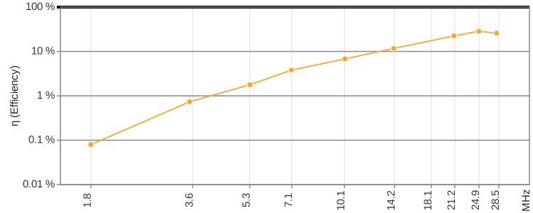
| Band | 160m | 80m | 60m | 40m | 30m | 20m | 15m | 12m | 10m | |
| Frequency f | MHz | 1.840 | 3.573 | 5.357 | 7.074 | 10.136 | 14.074 | 21.074 | 24.915 | 28.074 |
| Intrinsic bandwidth Bint | kHz | 3.7 | 5.7 | 11.9 | 17.0 | 40.0 | 87.0 | 231.0 | 359.0 | 645.0 |
| Source of Bint | SWR = 2.62 | |||||||||
| Loop diameter D | m | 1.006 | ||||||||
| Conductor diameter d | m | 0.100 | ||||||||
| Loop count n | 1 | 1 | ||||||||
| Inductance L | H | 1.51e-06 | ||||||||
| Capacitance C | pF | 4955 | 1314 | 585 | 335 | 163 | 84.7 | 37.8 | 27 | 21.3 |
| Unloaded Q0 | 1 | 497 | 627 | 450 | 416 | 253 | 162 | 91 | 69 | 44 |
| Damping resistance RT | Ohm | 0.0351 | 0.0541 | 0.113 | 0.161 | 0.380 | 0.825 | 2.192 | 3.406 | 6.120 |
| Radiation resistance RR | Ohm | 0.000028 | 0.000398 | 0.00201 | 0.00613 | 0.0259 | 0.0968 | 0.493 | 0.973 | 1.583 |
| Loss resistance RLoss | Ohm | 0.0351 | 0.0537 | 0.111 | 0.155 | 0.354 | 0.729 | 1.698 | 2.433 | 4.537 |
| Power to antenna Pfwd | W | 100 | 100 | 100 | 100 | 100 | 100 | 100 | 100 | 100 |
| swr_min | 1 | 1.00 | 1.00 | 1.00 | 1.00 | 1.00 | 1.00 | 1.00 | 1.00 | 1.00 |
| etaSWR_ant | % | 100 | 100 | 100 | 100 | 100 | 100 | 100 | 100 | 100 |
| Power antenna load Pload | W | 100 | 100 | 100 | 100 | 100 | 100 | 100 | 100 | 100 |
| Antenna efficiency η | % | 0.080 | 0.736 | 1.78 | 3.80 | 6.83 | 11.7 | 22.5 | 28.6 | 25.9 |
| Loop current I rms | A | 53.37 | 43.00 | 29.76 | 24.90 | 16.23 | 11.01 | 6.75 | 5.42 | 4.04 |
| Loop voltage Uloop rms | V | 932 | 1458 | 1513 | 1671 | 1561 | 1470 | 1351 | 1281 | 1077 |
| Magnetic dipole moment m | A m² | 42.448 | 34.199 | 23.669 | 19.803 | 12.910 | 8.754 | 5.372 | 4.309 | 3.215 |
| Link to calculator | calculator | calculator | calculator | calculator | calculator | calculator | calculator | calculator | calculator | |
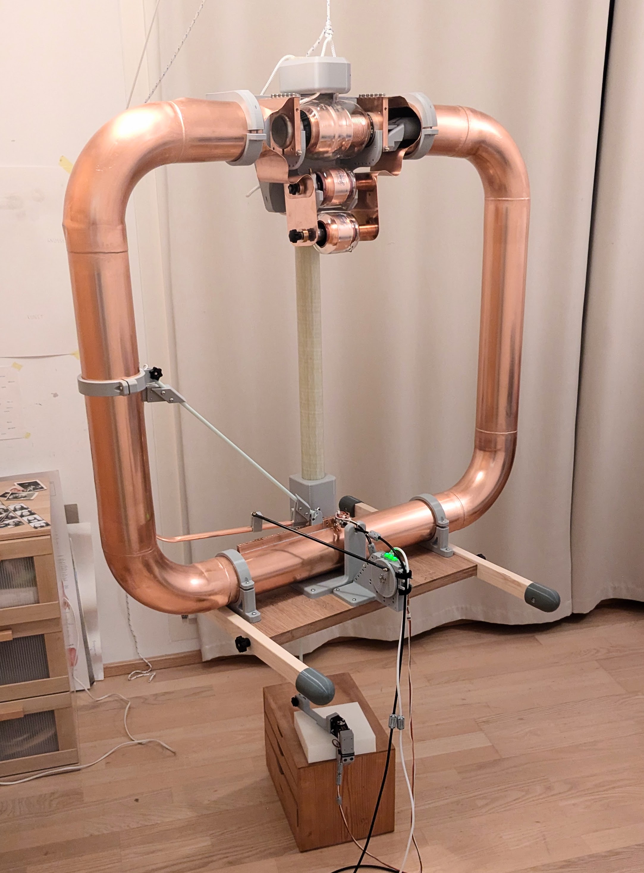
The antenna was suspended from the ceiling on the upper floor, about 0.8 m above the floor. Several indoor positions were tested; the position shown gave comparatively low damping. The house is built in timber-frame construction. Additional features include a green roof with moist soil, a nearby PV system, aluminum-coated underfloor heating, stainless steel canopies, and aluminum window frames. Together, these factors still make for a challenging indoor RF environment.
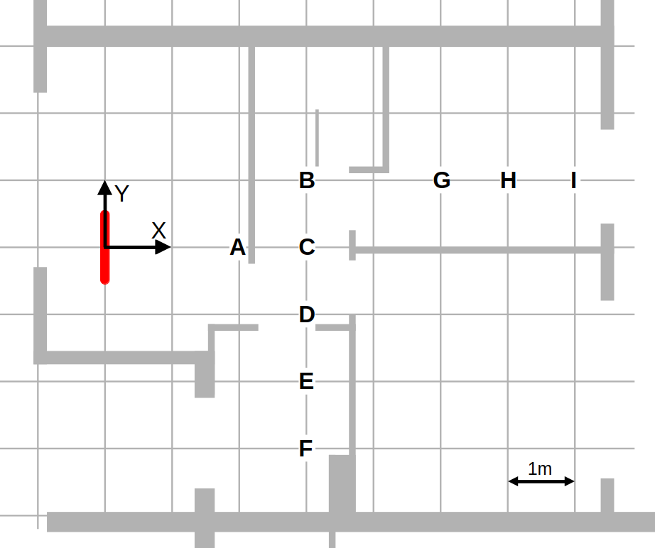
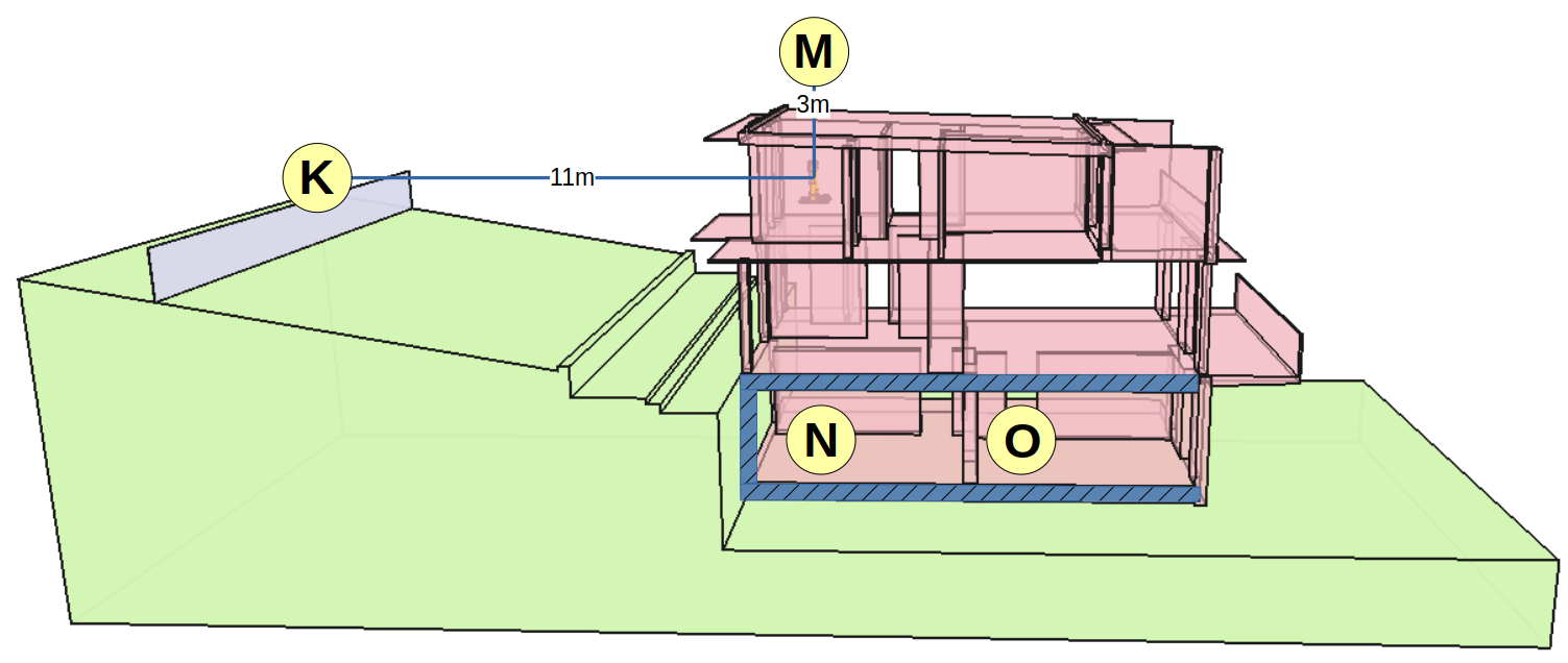
A detailed description is available here: https://arxiv.org/abs/2607.10828
Overview of all Antennas with filter/selection: compare page
Overview of all Antennas static: static compare page
2026 Peter Märki (HB9ISP). This project is created in my free time and has no commercial background. Provided without warranty of any kind. Feedback is welcome.